|
Motor Racing |
||||
|
|
||||
|
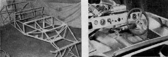
LOTUS
mark Xl COLIN CHAPMAN makes a habit of developing a prototype during the racing season for production the following year. The Mark XI for 1956 follows this policy and has a new chassis frame which differs appreciably from last year’s production cars. It is available, Lotus style, in the form of a kit of easily assembled parts. Although the chassis frame is multi-tubular in detail it is different, with the lower main tubes one inch square instead of round. The rest are 1 and 3/4 inch round tubes varying in thickness between 18 and 20 gauge. The
number of tubes are fewer, which has reduced the weight, but the
stiffness has been retained by means of a stressed floor tunnel of 20
gauge light-alloy sheet. The
swinging half-axle system has been retained at the front but the pivot
points have been lowered which should enhance even more the outstanding
cornering capabilities of the Lotus. The pivot bearings are within a
rigid steel channel section. This mounting makes for easy assembly of
the whole front suspension system and the Ford axle beams have been
“set” to allow for the lower roll centre. |
A new Girling-type suspension unit with built-in bump rubbers has been used. Morris Minor rack and pinion steering with three- piece column and two universal joints has been chosen and the wire wheels are 15 inch centre-lock Dunlops. Although
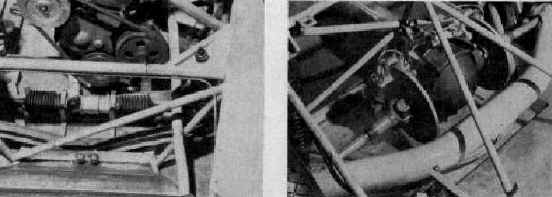
a De Dion rear axle system has been retained, it is entirely new.
Universal joints are within the ends of the tube, which is 3 inches in
diameter, a quarter of an inch larger than last year’s car. The De
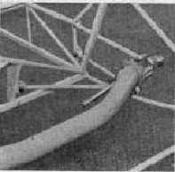
Dion tube is located by three tubular radius arms, two of which are
parallel fore and aft but the third forms a semicircle at the rear of
the chassis. Colin Chapman has had second thoughts about this as will be
seen in the captions to the photographs. The
axle ratios which will be made available are 4.89, 4.55, 4.22, 3.89 and 3.66 to 1. Inboard rear and outboard front
brakes are all Girling disc-type with 9-inch diameter discs and the
latest type caliper mechanism. The
prototype we examined had a Coventry-Climax engine installed in the
frame at an angle of 10 degrees which enables the height of the car at
the front to be |
lowered and makes available more space for carburetter installation. Two SU instruments were feeding from a remotely mounted float chamber on this car. The engine is supported at the rear by a part of the stressed floor tunnel. Cooling is by a fully-ducted cross-flow radiator, the light-alloy header tank of which is mounted on the chassis frame. In
unit with the Climax engine is a four-speed gearbox of special
manufacture with standard ratios of 1 to 1, 1.23 to 1, 1.67 to 1 and 2.5
to 1, and a reverse gear. In outward appearance the body is again aerodynamic but much lower than hitherto and with vestigial fins. The aerodynamic purpose of the fins on the earlier Lotus has been taken over by a head faring-type fin which is removable for ordinary road work. The body is four inches wider than last year and is well rounded at the sides making the cockpit roomy and easily accessible with neat drop-down light-alloy doors on each side. Complete car weighs 7 5/8 cwt dry. |
||
| |||||||||||||||||||||||||